
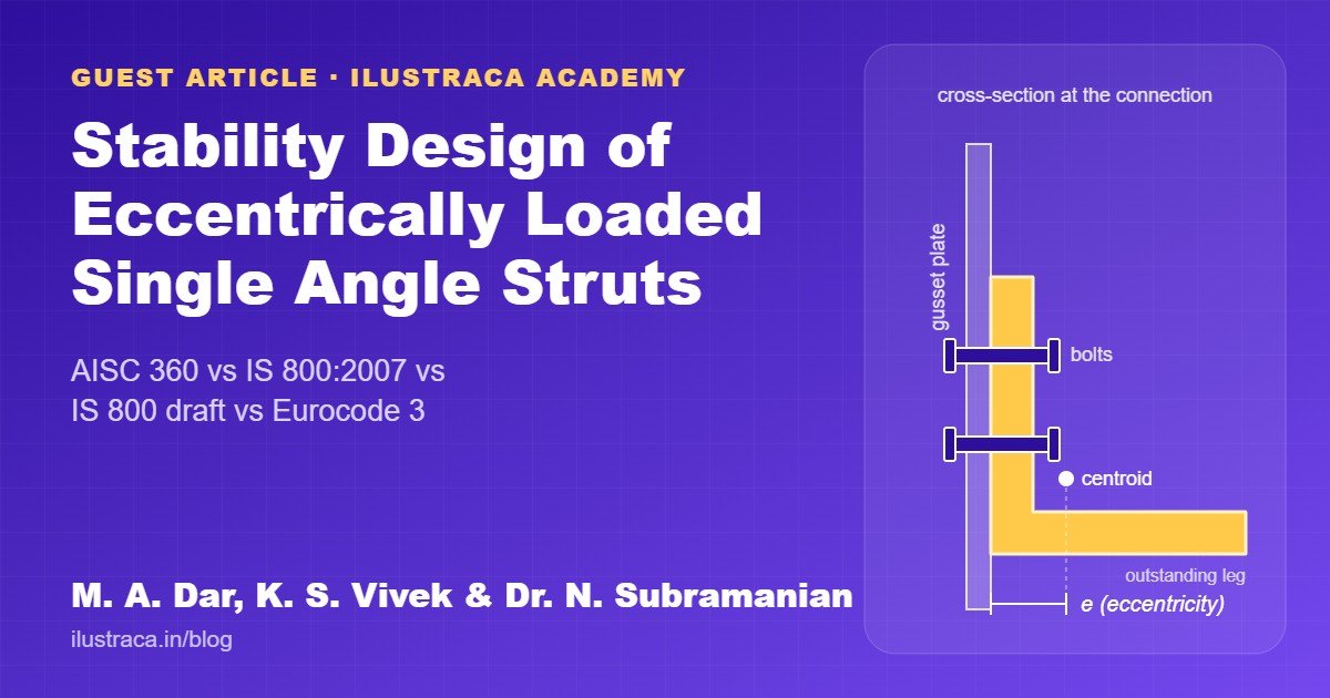

Single angles are everywhere: roof trusses, bracing in buildings and bridges, and transmission towers. They are cheap, easy to fabricate and quick to erect. But they are almost always bolted or welded to a gusset through one leg only, so the compressive force does not pass through the centroid. The result is a member that buckles and bends at the same time, and different design codes handle it very differently.
This paper by Mohammad Adil Dar, K. S. Vivek and Dr. N. Subramanian compares how four codes calculate the strength of such struts: ANSI/AISC 360:2022 (USA), IS 800:2007 and the IS 800:2025 Draft (India, the same provisions as Amendment 2 of 2024), and EN 1993-1-1:2005 (Europe). It then checks the codes against test results. The answer matters for every Indian designer, because the new draft IS 800 changes the method substantially.
How eccentrically loaded angles fail
- Angles under compression can fail by flexural buckling, torsional buckling or flexural-torsional buckling. Equal angles are symmetric only about the minor principal axis v-v, and unequal angles have no symmetry at all.
- Tests show that angle struts in trusses mostly buckle out of plane, perpendicular to the connected leg.
- The exact beam-column solution (Usami and Galambos, 1971) is reliable but too laborious for daily design. Codes therefore use a simplified “equivalent slenderness” method, in which the slenderness is modified to account for the eccentricity and end restraint.
- Angles with a single bolt at each end are noticeably weaker than those with two bolts because of stress concentration at the hole.
What each code does
AISC 360:2022 (Section E5)
The angle is treated as pinned, and the slenderness about the geometric axis parallel to the connected leg (ra) is modified:
L/ra ≤ 80: Lc/r = 72 + 0.75 L/ra
L/ra > 80: Lc/r = 32 + 1.25 L/ra
then the usual column curve (Section E3), with φc = 0.90.
This applies only to angles loaded through one leg with at least two bolts (or an equivalent weld), no transverse load and Lc/r ≤ 200. With a single bolt, the angle must be designed as a beam-column. Flexural-torsional buckling need not be checked when b/t ≤ 0.71√(E/Fy).
IS 800:2007 (Clause 7.5.1.2)
An equivalent slenderness ratio combines minor-axis flexural buckling and torsional buckling, with constants that depend on the number of bolts and on whether the gusset gives fixed or hinged rotational restraint (from Sambasiva Rao et al., 2003):
λe = √(k1 + k2λvv² + k3λφ²), then buckling class c (α = 0.49), γm0 = 1.10
| Bolts at each end | Gusset fixity | k₁ | k₂ | k₃ |
|---|---|---|---|---|
| ≥ 2 | Fixed | 0.20 | 0.35 | 20 |
| ≥ 2 | Hinged | 0.70 | 0.60 | 5 |
| 1 | Fixed | 0.75 | 0.35 | 20 |
| 1 | Hinged | 1.25 | 0.50 | 60 |
IS 800:2025 Draft (and Amendment 2, 2024)
The draft uses buckling about the a-a axis (parallel to the gusset) with buckling class b, multiplied by a factor Kf = k1 + k2λaa + k3λφ, so fcd = Kf χaa fy / γm0. For two or more bolts, the constants are 0.798, 0.563, −2.072 (fixed) and 0.401, 0.420, −1.040 (hinged).
EN 1993-1-1:2005 (Annex BB)
Flexural buckling with class b (α = 0.34) and γM1 = 1.0, using an effective slenderness for truss web angles: λeff,v = 0.35 + 0.7λv and λeff,y = λeff,z = 0.5 + 0.7λ. Like AISC, a single-bolted angle has to be designed as a beam-column.
The comparison
The authors calculated design strengths for five non-slender Indian equal angles (ISA 40×40×6 up to 130×130×16, IS 808:2021), each with two bolts at both ends and treated as hinged, for lengths of 0.5, 1.0 and 1.5 m and steel grades fy = 250, 350 and 450 MPa. For example, for ISA 75 × 75 × 10 in E250 steel:
| L/rv | AISC 360 | IS 800:2007 | IS 800:2025 Draft | EN 1993 |
|---|---|---|---|---|
| 34.0 | 209.4 kN | 190.8 kN | 131.5 kN | 223.7 kN |
| 68.0 | 176.8 kN | 165.2 kN | 148.1 kN | 195.7 kN |
| 102.0 | 145.0 kN | 133.7 kN | 152.1 kN | 171.9 kN |
Across all sections, normalised to AISC 360:
| fy | IS 800:2007 / AISC | IS 800:2025 Draft / AISC | EN 1993 / AISC |
|---|---|---|---|
| 250 MPa | 0.97 | 0.94 (scatter: SD 0.31) | 1.16 |
| 350 MPa | 1.13 | 1.17 (SD 0.38) | 1.38 |
| 450 MPa | 1.31 | 1.39 (SD 0.42) | 1.60 |
- AISC 360 and IS 800:2007 agree closely for E250 steel (mean ratio 0.97). The gap grows with higher-strength steel.
- Eurocode 3 gives the highest strengths for most practical slenderness: up to 16%, 38% and 60% above AISC on average for the three grades.
- The IS 800:2025 Draft behaves very differently. Its strength-to-yield ratio first rises and then falls as slenderness increases, unlike the near-linear trend of the other codes. Compared with IS 800:2007, it gives up to 59%, 69% and 79% more capacity for slender angles, but up to about 35% less for stocky ones. The crossover is at L/rv ≈ 64–68.
Checking against tests
The authors compared nominal strengths (all safety factors set to 1.0) with the few recent tests on two-bolted, hinged single angles, by Bhilawe (2017) and Kettler et al. (2019). A ratio below 1.0 means the code over-predicts the strength:
| Code | Mean Ptest / Pn | COV |
|---|---|---|
| AISC 360:2022 | 1.03 | 0.11 |
| IS 800:2007 | 0.96 | 0.10 |
| IS 800:2025 Draft | 0.76 | 0.28 |
| EN 1993-1-1:2005 | 0.80 | 0.12 |
AISC 360 and IS 800:2007 match the tests well. For the IS 800:2025 Draft and Eurocode 3, the specimens on average carried only 76% and 80% of the predicted strength, which is a safety concern.
What this means for designers
Based on the limited test data available, the authors recommend that eccentrically loaded single angle struts in plane trusses (with two or more bolts at each end) be designed, or at least cross-checked, using AISC 360:2022 or IS 800:2007.
- If you design to the new IS 800 draft or Amendment 2, cross-check slender angle struts with the IS 800:2007 equivalent-slenderness method.
- Do not treat single-bolted angles casually. AISC and Eurocode require beam-column design for them.
- For angles in transmission towers (space trusses), use the provisions of IS 802 (Part 1/Sec 2):2016 or ASCE/SEI 10-15 instead.
- More tests on eccentrically loaded angles are needed before any code can be fully calibrated.